|
The W3230 is not the easiest to configure at first. I find when setting the parameters, it likes to timeout if you wait too long to get the values set. So you have to be quick. Also, when changing values, if you hold the up or down button to scroll through values, it goes way to fast. But, once you get the hang of it, it goes fairly smooth. Having some patience with it is a must. The good thing is, once it's set up, you shouldn't have to ever modify it.
To change the temperature set point, momentarily press the SET button. The lower display, which shows the set point should now be flashing. Press the Up button to increase the value, or the Down button to decrease the value. When done press the Set button one more time or just wait a few seconds. If you are unable to change the set point, the unit may be locked. Continue reading below on how to unlock.
The W3230 has 9 parameters (P0-P8) that we will need to check and/or set before initial use. To change the settings, press and hold the SET button until P0 displays in the top display then release the SET button. To scroll through the various settings short press the SET button. Remember, if you wait too long, it will go back to the main display. When the parameter you want to change is displayed, press the UP or Down buttons to modify the setting.
If the values do not change, then the unit may be locked. To unlock, go to P7 and set to OFF. When it is set to ON, the other parameters as well as the set point can't be changed. This can be used to prevent unwanted changes.
The parameters we want to set:
P0 – mode = C or H [We want this set to C]
P1 – hysteresis = 0.1 to 15 (deg C) [set this to 1.0]
P2 – upper limit = up to 110 (deg C) [set this to 10]
P3 – lower limit = as low as -50 (deg C) [set this to 0]
P4 – temp correction = -7.0 to + 7.0 (deg C) [set this to 0]
P5 – delay start = 0 to 10 (minutes) [set to 10]
P6 – alarm temperature = (deg C) [set to OFF]
P7 – data lock = ON/OFF [set to OFF to allow changes to unit]
P8 – factory reset = ON/OFF [keep OFF, changing to ON will reset all values to default]
For more information on the W3230, see the Resources link below and check out the 2 videos also linked below.
|

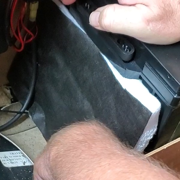
 When using LiFePO4 batteries that do not have a BMS (Battery Management System) with low temperature charging protection, here is a way to provide automated protection for them. In this article, I will discuss one method that is relatively inexpensive but, it provides decent protection. Whether you already have LiFePO4 batteries installed or are thinking about installing some that lack low temperature charging protection, this is an option that may work for you.
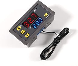 The controller we will be using is W3230 Digital Temperature Controller. It can be used to control a relay to turn it on if it is too cold (heating mode) or to turn it on if it is too warm (cooling mode). Since we only want our relay to be energized when it is warmer than our set point, we will be using the cooling mode.
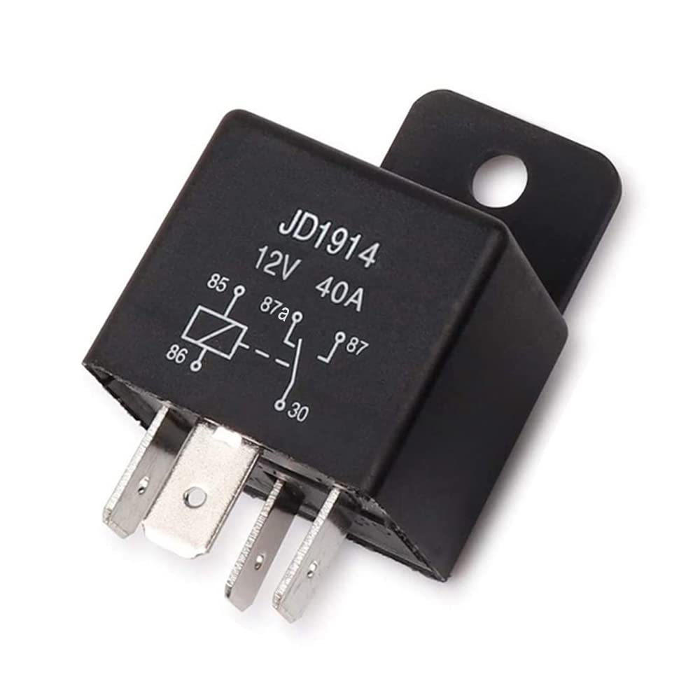 Bosch style 30A automotive relays work good with the W3230 Digital Temperature Controller. Depending on the number and type of charging methods, you may need more than 1 relay. The coils of the relays will be wired in parallel. Using multiple relays with the coils in parallel presents no issues as the output of the W3230 is rated for up to 20A. I recommend using a snubber diode on each of the relay coils to limit back EMF, but it is not required. The polarity of the diode must be observed. Connect the cathode to the +12V side of the relay and the anode to the grounding side of the relay coil.
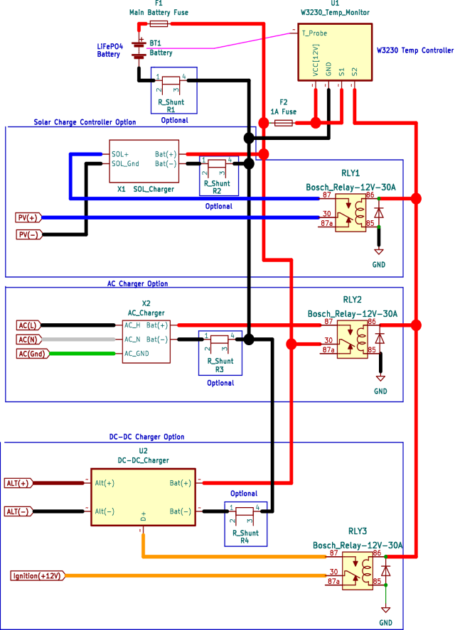
 With AC powered chargers 30A or under, I generally wire the N.O. (Normally Open) contacts to interrupt the DC output of the charger going to the battery. If we have a charger greater than 30A, you may need to use a higher capacity relay or possibly place a relay on the AC side of the charger. This would require a relay rated for at least 120VAC and the input current rating of the AC charger. I don't recommend the Bosch style automotive relays for 120VAC.
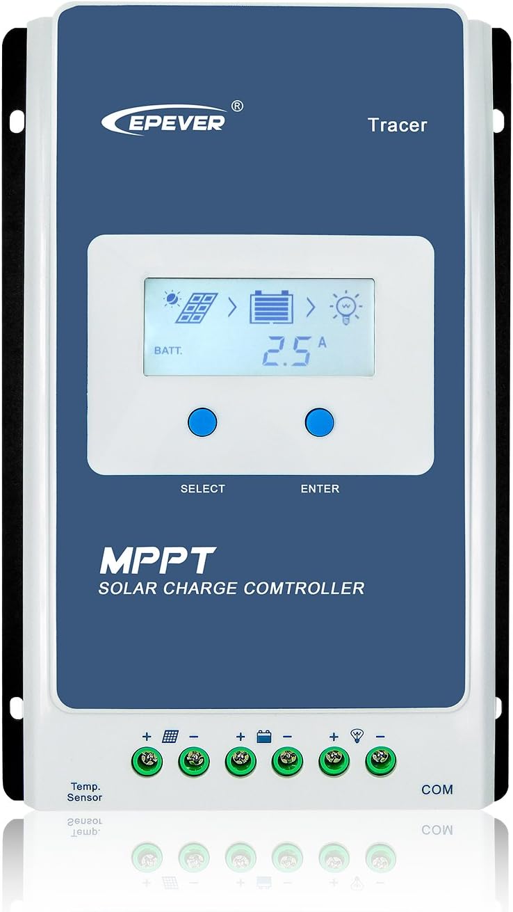 Most solar charge controllers recommend that the controller is connected to the battery prior to connecting the solar panels. So I suggest placing the relay to interrupt the solar panel input to the charge controller. If the output of your solar arrays is capable of greater than 30A, you may need to use a relay with a higher amp rating. While I don't recommend the following approach, you could also place more than 1 relay in parallel to increase the current capability. If you decide to follow this approach, I recommend fusing each leg going to each relay with a 30A fuse.
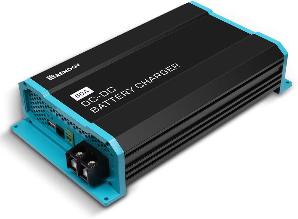 Most automotive DC-DC chargers will have an alternator or ignition switch sensing input. I use the relay to interrupt this signal to prevent the DC-DC charger from charging if the W3230 detects cold temperatures. This works great for high output chargers.