Common Voltage Systems Available
|
 |
|
There are several battery voltages
to use when designing a system for
your camper. This article will focus
on camper vans but it can be applied
to other RVs and campers as well. |
|
|
Probably the most commonly used voltage is 12V
and for a good reason, this is the voltage
already used by the vehicle itself. In
simple systems, this probably would be the
best solution. But in most other systems,
there are other voltage choices that
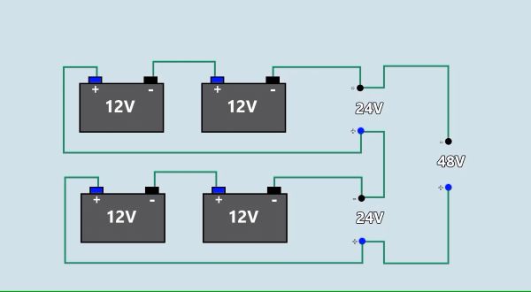
probably would be better. Other voltage configurations are based on multiples of 12V. These include 24V, 36V and 48V. Of these, the most popular is probably 24V with 48V gaining in popularity; however, 36V is seldom used. |

|
When needing more power for operating
appliances, especially over a longer cable
distance, using higher voltages have an
advantage. This is due to the fact that
higher voltages will deliver the same amount
of power using lower current. The current is mostly what determines what
gauge (size) of wire you need to use. Higher
voltage with lower current also means you
will have less power loss. Plus, being able
to use smaller gauge wire, means lower
system cost and lower weight. With a simple
system, this may not amount to much, but as
the complexity grows, it becomes more
important. |
|
On most camper van builds, I gravitate
towards using 24V. This will keep our
current flow to half of that of 12V. But, we
will still need 12V and 120VAC for many
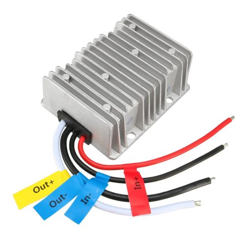
items. For 12V items, I will use a 24V to
13.8V DC-DC converter rated at 40A. This
will be used for lighting, vent fans and
other relatively low power items. For higher
powered items, I will use 120VAC and
sometimes 24V. The current flow for 120VAC
will be about 1/10th of that for 12V for the
same amount of power delivered.
|
|
ABYC Wire Sizing
|
|
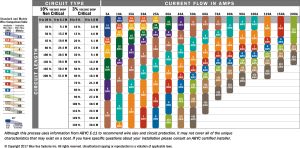
The American Boating and Yacht Counsel
(ABYC) has a wiring standard E-11. A wiring
chart can be found at www.BlueSea.com/resouces/1437
. This is a good resource to use for
determining the recommended wire gauge to
use. There are two columns on the left that
list lengths of wire for critical (no more
than 3% voltage drop) and non-critical (no
more than 10% voltage drop). Since a wire
run is a loop (power to on positive and
power return on negative), you will need to
double the physical length of cable for
looking up in chart. I explain this and how
to use the chart in a youtube video.
|
|
Auxilliary Power Unit
|
|
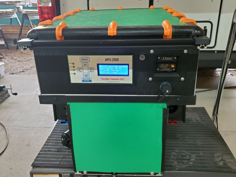
| I
typically bundle the LiFePO4 battery
cells, Battery Management System
(BMS), 3KW Sine Wave Inverter, AC
charger, Solar MPPT charger and a
24V to 13.8 DC-DC Converter all into
one package which I call an
Auxillary Power Unit (APU). This
keeps the inverter close to the
battery to minimize power loss. |
|
|
The package is completed by
including a microcontroller, display
and keypad. The microcontroller
communicates with other controllers
in the van using PCAN (Purrfect
Campers Area Network) which is a
specific CAN Bus protocol very
similar to OBDII used in all
vehicles today. This allows the APU
to be monitored and controlled with
a PCAN tablet or it can be
controlled using it's own keypad.
With all that said, the APU can be
removed from the van and used as a
stand alone power source since all
of it's external connections easily
unplug from it. |
|
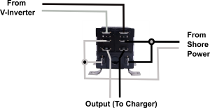
A
really cool feature of the APU is,
once you select automatic mode, it
will turn the inverter
on whenever there is no shore power and there is no
power from the V-inverter (I'll
discuss the V-inverter a little
further down in this article). |
 |
|
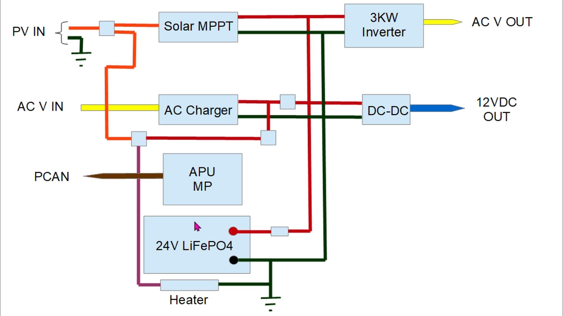
Taking a look at the wiring diagram
for the APU, the orange lines
represent the solar power coming in.
The red lines are the 24V bus. The
blue line is for 13.8V out. The
yellow lines are 120VAC. The black
lines are ground. The small
unlabeled square boxes are for
relays/contactors. Their main
purpose is to prevent charging when
the battery temperature is near or
below freezing. They will instead
divert power from the charging
source (solar or ac charger) to a
heating pad to warm the batteries.
Note that this uses power from the
charger sources and not the battery
itself. |
|
|
V-Inverter
|

|
One thing you will notice, is the APU
doesn't have DC-DC charging from the
engine's alternator. This is done using a
different method you probably haven't seen
before. I use a V-Inverter which is usually a 12V to 120VAC 2K
watt sine wave inverter placed under the
driver's seat and is connected to the van's
battery. It is switched on automatically
when the van is runing and the alternator is
putting out at least 13V. The advantages of
using this method include less loss of power
through long runs since the APU is generally
located at the back of the van, 120V is
available in the van without consuming power
from the APU, and reduced system cost since
we only need to run a 12 AWG power cable
between them.
|
|
Transfering Power
|
|

|
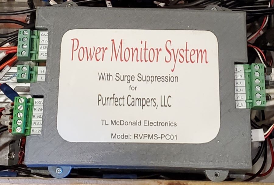
In the Omnia, the
120VAC power sources are all
controlled using the Power
Management System (PMS). It uses
small transfer contactors to control
which source to select from. An
alternative option is to use a
transfer contactor with a 120VAC
coil to swap between sources.
Transfer contactors are important
to prevent one source from feeding
power back to another source.
|
|
|
|
|
|

|

|

|
Discuss in ProBoard Forum
|
List of Resources
|
Video
|
|
|